Michelson interferometer fringes with laser or white light.
Primary tabs
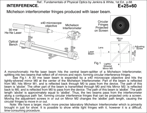
Ref.: Fundamentals of Physical Optics by Jenkins & White, 1st Ed., p.68 A monochromatic He-Ne laser beam hits the central beam-splitter of a Michelson Interferometer, splitting into two beams that reflect off of mirrors and rejoin, forming circular interference fringes. See Fig.1: A 30 mw laser beam is expanded by a x40 microscope objective and hits the lightly-silvered mirror M0 at the center of the Michelson Interferometer. Part of the beam is reflected from M0; hits Mirror M1, and is reflected back through M0 to pass from the device. The path of this beam is 'abcbe'. The other part of the beam is transmitted through M0 and hits Mirror M2; is reflected back to M0, and is reflected from M0 to pass from the device. The path of this beam is 'abdbe'. The path length 'abcbe' is approximately equal to 'abdbe'. Thus, the two beams pass from the interferometer along a contiguous path 'be', forming circular interference fringes that can be projected onto a screen. Moving the adjustment screws in or out on Mirror M2 changes the 'abdbe' path length, causing the circular fringes to move in or out. Note: We have a larger, much more precise laboratory Michelson Interferometer which is primarily brought in just for show. It is possible to show white light fringes with it, however it is a difficult, time-consuming procedure.
UCB Index:
E+25+60
PIRA Index:
6D40.10
UCB Taxonomy:
PIRA Taxonomy:
Popularity:
- Log in to post comments

