Phases of V and I in series circuit as RL shifts to RC.
Primary tabs
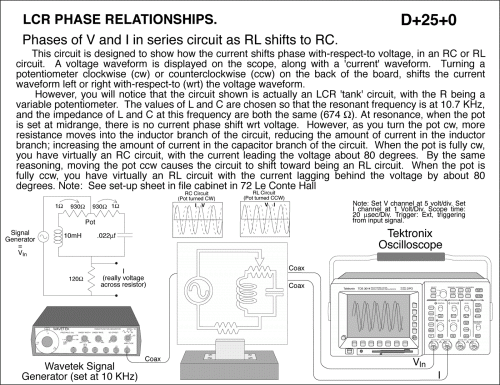
Phases of V and I in series circuit as RL shifts to RC. This circuit is designed to show how the current shifts phase with-respect-to voltage, in an RC or RL circuit. A voltage waveform is displayed on the scope, along with a 'current' waveform. Turning a potentiometer clockwise (cw) or counterclockwise (ccw) on the back of the board, shifts the current waveform left or right with-respect-to (wrt) the voltage waveform. However, you will notice that the circuit shown is actually an LCR 'tank' circuit, with the R being a variable potentiometer. The values of L and C are chosen so that the resonant frequency is at 10.7 KHz, and the impedance of L and C at this frequency are both the same (674 ohms). At resonance, when the pot is set at midrange, there is no current phase shift wrt voltage. However, as you turn the pot cw, more resistance moves into the inductor branch of the circuit, reducing the amount of current in the inductor branch; increasing the amount of current in the capacitor branch of the circuit. When the pot is fully cw, you have virtually an RC circuit, with the current leading the voltage about 80 degrees. By the same reasoning, moving the pot ccw causes the circuit to shift toward being an RL circuit. When the pot is fully ccw, you have virtually an RL circuit with the current lagging behind the voltage by about 80 degrees. Note: See set-up sheet in file cabinet in 72 Le Conte Hall
UCB Index:
D+25+0
PIRA Index:
5L20.10
UCB Taxonomy:
PIRA Taxonomy:
Popularity:
- Log in to post comments

