Standing waves on two parallel wires, with 510 transmitter.
Primary tabs
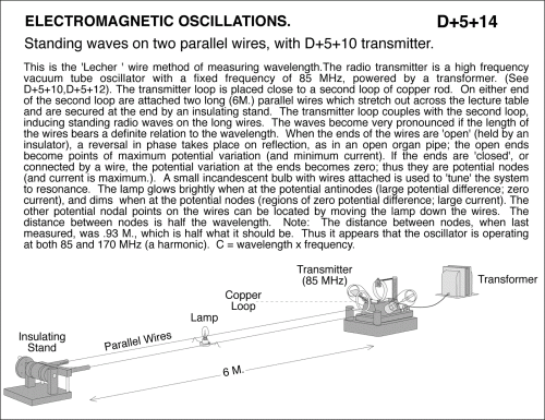
Standing waves on two parallel wires, with D+5+10 transmitter. This is the 'Lecher ' wire method of measuring wavelength.The radio transmitter is a high frequency vacuum tube oscillator with a fixed frequency of 85 MHz, powered by a transformer. (See D+5+10). The transmitter loop is placed close to a second loop of copper rod. On either end of the second loop are attached two long (6M.) parallel wires which stretch out across the lecture table and are secured at the end by an insulating stand. The transmitter loop couples with the second loop, inducing standing radio waves on the long wires. The waves become very pronounced if the length of the wires bears a definite relation to the wavelength. When the ends of the wires are 'open' (held by an insulator), a reversal in phase takes place on reflection, as in an open organ pipe; the open ends become points of maximum potential variation (and minimum current). If the ends are 'closed', or connected by a wire, the potential variation at the ends becomes zero; thus they are potential nodes (and current is maximum.). A small incandescent bulb with wires attached is used to 'tune' the system to resonance. The lamp glows brightly when at the potential antinodes (large potential difference; zero current), and dims when at the potential nodes (regions of zero potential difference; large current). The other potential nodal points on the wires can be located by moving the lamp down the wires. The distance between nodes is half the wavelength. Note: The distance between nodes, when last measured, was .93 M., which is half what it should be. Thus it appears that the oscillator is operating at both 85 and 170 MHz (a harmonic). C = wavelength x frequency.
UCB Index:
D+5+14
PIRA Index:
5N10.50
UCB Taxonomy:
PIRA Taxonomy:
Popularity:
- Log in to post comments

