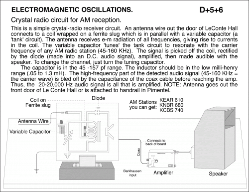
Crystal radio circuit for AM reception.
Primary tabs
Crystal radio circuit for AM reception. This is a simple crystal-radio receiver circuit. An antenna wire out the door of LeConte Hall connects to a coil wrapped on a ferrite slug which is in parallel with a variable capacitor (a 'tank' circuit). The antenna receives e-m radiation of all frequencies, giving rise to currents in the coil. The variable capacitor 'tunes' the tank circuit to resonate with the carrier frequency of any AM radio station (45-160 KHz). The signal is picked off the coil, rectified by the diode (made into an D.C. audio signal), amplified, then made audible with the speaker. To change the channel, just turn the tuning capacitor. The capacitor is in the 45 -157 pf range. The inductor should be in the low milli-henry range (.05 to 1.3 mH). The high-frequency part of the detected audio signal (45-160 KHz = the carrier wave) is bled off by the capacitance of the coax cable before reaching the amp. Thus, the 20-20,000 Hz audio signal is all that is amplified. NOTE: Antenna goes out the front door of Le Conte Hall or is attached to handrail in Pimentel.
UCB Index:
D+5+6
UCB Taxonomy:
Popularity:
- Log in to post comments

