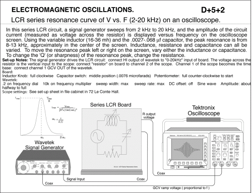
LCR series resonance curve of V vs. F (2 - 20kHz) on an oscilloscope.
Primary tabs
LCR series resonance curve of V vs. F (2 - 20kHz) on an oscilloscope. In this series LCR circuit, a signal generator sweeps from 2 kHz to 20 kHz, and the amplitude of the circuit current (measured as voltage across the resistor) is displayed versus frequency on the oscilloscope screen. Using the variable inductor (16-36 mh) and the .0027-.068 micro f capacitor, the peak resonance is from 8-13 kHz, approximately in the center of the screen. Inductance, resistance and capacitance can all be varied. To move the resonance peak left or right on the screen, vary either the inductance or capacitance. To change the 'Q' (or sharpness) of the resonance peak, change the resistance. Set-up Notes: The signal generator drives the LCR circuit: connect HI output of wavetek to "0-20kHz" input of board. The voltage across the resistor is the vertical input to the scope: connect "resistor" on board to channel 2 of the scope. Channel 1 of the scope becomes the time base: connect channel 1 GCV OUT of the wavetek. Inductor Knob: full clockwise; Capacitor switch: middle position (.0076 microfarads); Potentiometer: full counter-clockwise to start; .2 on frequency dial; 10k on frequency multiplier; sweep width: max; sweep rate: max; DC offset: off; Sine wave Amplitude: about halfway to full; See set-up sheet in file cabinet in 72 Le Conte Hall.
UCB Index:
D+5+2
PIRA Index:
5L20.11
UCB Taxonomy:
PIRA Taxonomy:
Popularity:
Previous:
- Log in to post comments

